Build Your Own Solar Water Heating Panel
Further Solar Reading and Links:
economical Selenium photo voltaic cells
Tools and materials
The flat plate collector, or solar panel, is relatively easy to construct and should present few problems to the average handyman. If you can install a sink unit, plumb in a washing machine, make a bookcase, then this project should not be too difficult. An entire novice plumber may need a little help. The panel can be constructed without the aid of special tools, specialist materials, or ‘secret’ processes. A hacksaw, wood saw, drill, hammer, screwdriver, nails, screws, paintbrush, file and a tape measure are the tools you will need most. The materials needed are, 10 mm annealed copper tube, 16 swg aluminium sheet, timber for making a frame, glass fibre wool, marine-ply sheet, and 4 mm glass. These items can usually be obtained locally from a good hardware shop, plumber’s merchant, or from a mail order company specialising in the DIY market. The actual sizes, quantities and specifications will be dealt with a little later on.
Efficiency
The panel has been designed with 3 main considerations. The first is efficiency. It is not the most efficient panel design but it does give very good results. Solar panels usually have an efficiency rating somewhere between 40% and 60%. This panel should give approximately 50% of the energy it collects, making it comparable with most commercially available units.
Cost
The second consideration is cost. You can construct this panel for about 1/3 rd of the price of a purchased panel, and even less if you can build from salvage materials. The sun’s energy is free, so the less you spend on installing the solar water heating system the sooner your initial outlay will be paid back, and the longer will be the period of free energy collection. Which brings us to the third consideration; durability.
Durability
The longer the panel can provide useful energy the more attractive is the case for installing a solar water heating system. If carefully constructed, the panel should have a useful life expectancy of 20 years or more. The materials used will not deteriorate rapidly and as there are no moving parts there is nothing to wear out. There is virtually no maintenance required. Experience shows that dust and grime on the glass cover do not impede the collection of solar energy. Occasional checks to make sure that the glass cover is not cracked, the wood frame is not warping, and the system has not developed leaks are all that is needed.
Tubing
The panel uses copper tubing to carry the domestic water through its collector area. Copper is universally acceptable for plumbing and water systems. It does not corrode in oxygenated water, and so long as a suitable inhibitor is used it will not corrode in water/ethylene and glycol mixtures either. Copper has high thermal conductivity properties, essential to provide efficient transfer of collected solar heat to the water supply. The existing plumbing in your home will almost certainly be copper and the new solar heating system should be copper also to avoid the corrosion problem associated with mixed metal systems. Copper is not cheap. However, the 10 mm copper tubing is mass produced and is readily available in 20 m and 25 m and 30 m coils. It can be purchased at most DIY plumber’s merchants. It is soft and easy to work into the desired shape.
Absorber plate
The copper tubing will be attached to the blackened absorber plate. This plate will collect the sun’s radiant energy and transfer it to the water filled copper tubing. The plate should be made from aluminium or copper to achieve the best results. Aluminium, being cheaper than copper and more readily available in most areas, is a good proposition. A thickness of 16 swg is preferable as thinner gauges tend to warp under intense heat conditions and thicker gauges give reduced efficiency. The absorber plate will be painted with black paint and primer and so will the copper tube, so there will be little risk of galvanic corrosion.
The absorber plate will be housed in a wooden tray. The tray is made from a hardwood frame with a marine-ply backing sheet. A good preservative coating should be applied to the tray to ensure minimum maintenance during its exposed life.
Transparent Cover
The panel should be covered with a transparent sheet to prevent heat loss in cool weather. Glass is preferred because it is readily available and has a high light transmission value. It will ‘trap’ long wave radiation, thus improving the efficiency of the panel. 4 mm float glass should be used. Acrylic sheeting can be used, and this will result in a lighter panel. Acrylic is usually much cheaper than float glass, but bear in mind that glass does not scratch or discolour. The transparent cover can be placed in the tray and sealed with wood beading and a suitable gum or resin.
Other items you will need are: glass fibre wool (the type used for loft insulation), a few sheets of aluminium foil or highly reflective ‘lunar’ foil or Mylar Aluminised Film, black paint and primer and a collection of wood screws, nails, wire etc. Plumbing materials will be discussed later. The measurements given should be followed as closely as possible. Experimentation with most types of solar collectors before deciding on the design given here, and recommendations that there be as much standardisation as possible in the construction of the panels so that results can be easily compared. However, should you have access to less expensive materials or slightly different dimensions and properties, then by all means use them.
CONSTRUCTION DETAILS
By following these construction details you will be able to build a solar panel 1500 mm by 900 mm, giving just under 13500 mm2 collector area. Two or three panels will be sufficient for the average household (4 people) and you should refer to the following chart in order to ascertain how many panels you will require. This chart applies only to climatic conditions similar to those in the British Isles.
Domestic Heating Installations
|
No. of panels required |
Cylinder or tank capacity |
|
1 |
15 gallons |
|
2 |
30 – 35 |
|
3 |
35 – 50 |
|
4 |
50 – 70 |
The panel must be able to drain down in cold conditions to prevent the water and the copper tubing from freezing. Water in solar panels can sometimes freeze when the outside air temperature is slightly higher than freezing point. The alternative is to use an indirect or closed circuit system and to add anti-freeze to the water. This requires a heat exchanger in the hot cylinder tank so that the anti-freeze/water mixture is kept separate from the domestic water supply. The panels are versatile and can be used in either system. Construction can be broken down into 5 main parts:
1. Panel tray and frame
2. Absorber plate
3. Copper tubing
4. Insulation
5. Glazing
PANEL TRAY AND FRAME
The panel frame should be 1500 mm x 900 mm x 80 mm. Decide on the method for making the corners  (Fig.1) and purchase the wood accordingly. A good hardwood should be used such as teak or cedar. Most timber merchants will cut the wood to length, and machine it if desired. The 80 mm x 50 mm section is advised.
 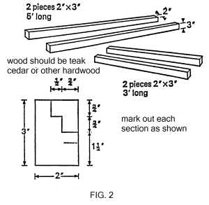 (Fig.2 for section detail) . Good corner joints are essential to achieve good weather-proofing. The rebates or lips for receiving the collector plate and glass can be cut out with a circular saw and the cut out strips used as beading for the glazing. After the frame has been constructed two holes of 11mm (7/16″) diameter should be drilled in the sides of the frame to accommodate the copper tube inlet and outlet. They should be drilled 2″ from the top or bottom of the frame as required. If using two panels in your system then you will require one left hand and one right hand panel
 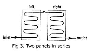 (Fig.3) so that both panels connect at the top centre position. Inlet and outlet will be at opposite bottom corners to facilitate draining the panels in cold weather. If using three or more panels in parallel connection
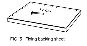
 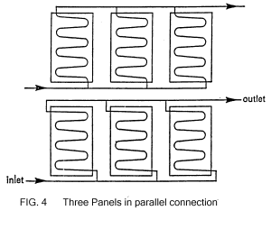 (Fig.4) then all the panels can be of the same hand. The frame can now receive its backing sheet. This should be of marine ply quality for best results, but 4mm (5/16″) exterior grade plywood can be used. Measure the frame exactly and cut the backing sheet accordingly. Place the sheet in position and nail to bottom side of frame
  (Fig.5). An alternative method is to machine a rebate in the frame roughly 1/4″ from the bottom and slide in the backing sheet before putting the fourth side of the frame in place. This will give a neater and more durable finish. The whole frame and backing sheet should now be coated with a good wood preservative to ensure a lasting finish.
ABSORBER PLATE
Purchase and treatment of aluminium sheet
Purchase enough aluminium sheets of about 4’8″ x 2’8″ x 16swg for your needs (or an appropriate size to fit into the constructed tray). Look in your Yellow Pages for aluminium stockists and contact a few to gather quotations before deciding to purchase. Prices from stockists can vary considerably. Aluminium type H9 or similar is suitable.
Clean the aluminium on both sides and remove any trace of oil that may be present. Turn up the shiny side of the sheet and use some emery paper to etch the surface. This will remove small traces of oil and allow the paint to adhere to the surface better. Go all over the aluminium sheet in small circular rubbing movements. Next apply a good primer such as zinc chromate or red oxide. It is best to obtain the paint and primer in aerosol form to achieve the flatest possible coating on the absorber plate. It will also dry quicker and give an attractive finish. Small aerosol cans can be expensive for the amount of paint supplied, a large aerosol can will give better value for money. U-Spray comes in 400g (140oz) cans and is marketed by Borden (UK) Ltd., Southampton, SO5 9ZB. Their matt black is very good and has quite a high radiation absorption rate. Two cans will be enough to cover three absorber plates. The paint dries quickly (usually within ten minutes) and becomes very hard if left overnight  (Fig.6).
COPPER TUBING
Purchasing and shaping of copper tube
The next step is to produce the serpentined copper waterway tubing. Using the diagrams (Fig.9) work out how much copper tubing you will need. 30′ to 35′ (10 meters) is about right. The more copper tube the better, up to a point. The type to obtain is 10mm annealed. It isused extensively in central heating systems and is obtainable from any good plumbers’ merchant, DIY central heating shop, or from the numerous mail order central heating companies that advertise in magazines like Exchange & Mart. It comes in soft coils of varying lengths and is very easy to work into shape. If care is taken the copper tube can be shaped by bending it around a cylindrical object like a bottle  (Fig.7). A small hand bending machine such as the Preston Hand Bender is ideal and will ensure a perfect bend, resulting in good water flow through the system. As copper is very soft metal it is easy to flatten or squash the tube when making a bend without the aid of a forming machine, so if you are bending by hand make sure that you bend the tube gradually. It may be time-consuming but you will avoid kinking the pipe which could result in furring caused by restricted water flow, thus reducing efficiency. Should you kink or squash the pipe you may be able to get it back into shape by placing it on a piece of wood and tapping it with a wooden mallet. You will find the best method of bending the tube is first to draw off some tube from the coil and straighten it out on the floor
 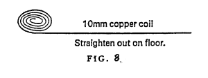 (Fig.8) so that you have a long straight piece of copper to bend rather than bending from the coil. Then keep bending
 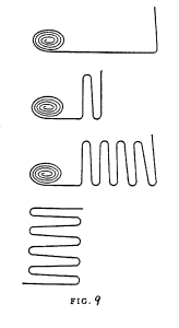 (Fig.9) until you have the required shape (refer back to Fig.6). The formed tube should be hung from a piece of wire and sprayed with the matt black paint.
Attaching copper tube to absorber plate
When the paint is dry, place the formed copper tube on top of the aluminium absorber plate (black side) with a slight rise on each cross piece so that the water will always run down to the bottom outlet to drain  (Fig.10). Using white chalk mark out the pattern of the copper tubing onto the black absorber plate, and remove the copper tube. Next drill a series of small holes, two on either side of the cross piece of tubing (Fig.6). These holes will take the wire that will hold the tube closely against the absorber plate to achieve efficient heat transfer to the water in the tube. Next place the formed copper tube onto the plat and start threading a good strong wire through the holes and over the copper tube. A single piece of wire will do the job. Thread one end of wire through a starting hole, over the tube, and out through the second hole, continuing this lacing process until the final hole is reached and all of the cross pieces have been covered. The more loops the better to give good thermal contact between the copper tube and the absorber plate. An alternative method is to use small copper clips at each fixing point, they can be fixed in position with small self-tapping screws or small nuts and bolts. You may have difficulty in obtaining these clips as most small bore pipe clips are now plastic and unsuitable for high temperature work. Copper tube can also be soldered to the aluminium sheet using special solder and flux but the process has to be delicately controlled and is not for the amateur handyman.
INSULATION
Glass fibre wool and aluminium foil
The absorber plate is now ready for insertion into the panel tray, but first the insulation must be in place. 3″ glass fibre wool should be laid in the tray. This will compress when the absorber plate is lowered on top of it  (Fig.11). A layer of aluminium baking foil can be sandwiched between the glass fibre wool and the plate with the shiny side to the plate. This will help stop heat loss by reflecting heat back to the plate.
Lower the absorber plate into the tray making sure that the inlet and outlet pipe ends are first bent back and then inserted through the 11mm (7/16″) holes in the sides of the panel  (Fig.12). The plat can be held in place by strips of wood beading screwed to the sides of the inner frame. A final spray of matt black paint is needed to mask any scratches on the paintwork caused by the wire and to cover the inside wall of the wooden frame.
GLAZING
Inserting glass sheet
The panel is now ready for glazing. 4mm (320z) float glass is the recommended quality for this size panel. 3mm float glass can be used in panels up to 10 sq.ft. but is too fragile for larger areas. The light transmittancy of 4mm glass is approximately 88% to 90% with a reflectance of 8%. Thicker glass will have slightly lower transmittance. Handle the glass very carefully and ask the glazier to deliver if this is possible. Measure the inside of the frame accurately and have the glass cut to size. There should be a gap of 15mm (1/2″) between the top of the copper piping and the cover 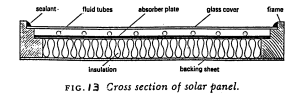 (Fig.13). A larger gap will result in lower efficiency. After placing the glass in the tray, secure with wood beading and seal with a good sealant to keep out moisture.
Now that the panels are constructed they should be stored in a safe place until required. Store them upright so that the tube inlets and outlets will not be damaged. The panels will be heavy and help should be obtained when moving them.

Standardized Gas
The calibration of emissions monitoring equipment, fuel detection systems
or basic research analysers requires appropriate,
reliable calibration gases coming from a responsive and knowledgeable supplier.
Our goal is to go beyond these requirements and provide a new benchmark service to the analytical sector.
It is widely identified that frequent calibration applying gas mixtures is the best approach to
ensuring your analysis as well as detection system is
free from go and performs to the authentic manufacturer’s specifications.
But adjusted gases are typically subject to lengthy lead times, multitudinous choices and inflexible package sizes – do you really want in which large rented
cylinder for a one-off research project?
We take another view to the supply of standardized gas – one that provides the right option for your requirements protected by the best support and also service in the industry.
It will begin with the package options; basic rented refillable cylinder choices available in a wide range of sizes, from the compact 2 and
seven litre models which are well suited for on-site work to the
substantial 50 litre cylinders that provide ample gas capacity for automated calibration protocols.
In addition to this, calibration gases are available in our a relatively inexpensive nonrefillable
(disposable) cylinder choices, providing smaller quantities of gas without
the ongoing expense of rental arrangements for occasional research
demands or feature checking of portable natural gas detectors.
Our application professionals will be delighted to help you
pick the right option for your demands.
Great article. But other sites suggest that using copper tube in the panel is not wise because of high risk of rupture in frost conditions. The recommendation is to use silicone tube instead. Do you have a view on this?
He is talking about emtpying the pipe before winter ! The metal pipe conduct heat better
sir, iwant to make these type of solar system for home plz if u can send detailsof this we are very greatful of u.
Excellent article. Could use a little clarification in some parts and a little expanding but overall well done. I appreciate it. Thank you.
Hi Mark, if you have any information that would update or mprove the DIY Solar Page, please let me know and I will do what I can.
Very good information lots to think about now.
Andrew
I appreciate those who share ideas on u tube.
I want to cut my heating bill by making a 4×8 type panel to see how good it will work. Any advice will be much appreciated.
Our current home is all electric. I don’t have the cash to spend for a solar system as many do.
So I am trying to come up with a different plan. Our bills in cold weather run over $300. for a home just over 1200 scrare feet. I have around 9 inches of insulation in the roof. The walls are only 4 inch insulation with brick.
Thanks,
Dave